
The Vaisala RS41 and RS41-SG are, currently, among the most popular Radiosonde attached to the weather balloons that are regularly launched by many different weather forecast agencies.
The radiosonde is an interesting device that has, onboard, few sensors used to get weather-related information as temperature, pressure, humidity, GPS, and some other sensors. It has also a low power TX transmitter to transmit continuously the sensor data and the GPS position.
It is usually not so difficult to find one through “radiosonde chasing”. There is a growing community of users interested in “radiosonde chasing” and many dedicated web sites with information and realtime radiosonde tracking. Some links at the end of this post.
It is possible to re-purpose the radiosonde for other uses; for example to attach it to an amateur balloon or to experiment tracking a device or, maybe, an animal like a dog. But there is a problem: it is illegal to use the same frequencies used by the weather agencies.
Ham radio operators can legally use Ham radio frequencies to experiment with the radiosonde, to do so it is needed to change the TX frequency and the callsign of the Radiosonde.
Few smart peoples (like Rolf DF9DQ and Mirko IZ4PNN) have found a way to access the RS41 configuration menu through the UART interface that has quite interesting available commands as:
- Fre(q)uencies menu, to change the TX frequency, but only between 405.00 and 405.99, outside of Ham radio bands
- TX p(o)wer menu, to change the TX power from 0 to 7. It can be useful to select “0”, during testing, to reduce the probability that the transmission will be received by some monitoring station. The radiosonde will switch to power level “7” when in “flight mode”, probably it will enter in “flight mode” above a specific altitude (1 km ?)
- T(X) state menu, to disable transmission. It can be useful to prevent transmission during testing. This option will not survive reboot cycles, the previous options, instead, will survive reboots
- Ser(i)al no menu, to input the callsign of the radiosonde, it is possible to put the ham radio callsign; this callsign will survive reboots, but the TX frequency at startup is the one selected with the “Frequency” menu that is outside of the amateur radio bands
- (T)X registers menu, this is quite interesting because it is possible to read or write the register values used to program the TX chip, the Silicon Labs Si4032, in this way it is possible to select the tx frequency inside the 70cm radio amateur band (430-438Mhz). There are only 3 registers (0x75, 0x76, and 0x77) that control the TX frequency. The above calculator will give these register values. Unfortunately, these values will not survive reboots. After reboot, the value selected with the “Frequencies” menu will be the TX frequency
How these register values are calculated
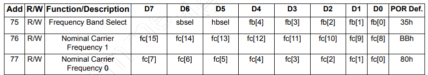
According to the Silicon Labs Si4032 datasheet on page 22, the registers that control the TX carrier frequency are the registers 0x75, 0x76, and 0x77:
According to the datasheet we have to select the band we are interested in with:

- hbsel (High Band select, 1 bit: 0 or 1) to select the lower or higher frequencies
- fb (Frequency band select, 4 bit: from 0 to 15) to select the band according to the table on page 23
But the datasheet assumes that we have a 30Mhz crystal, instead on the RS41 we have a 26 Mhz crystal, this means that all the frequencies must be “re-scaled” multiplying them by 26/30. For this reason the following table on page 23: 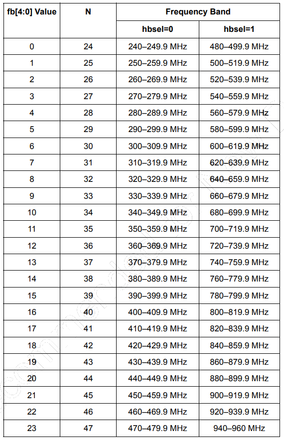
must be “re-scaled” and the correct one is the following, please note that, for simplicity, numbers are rounded to the nearest integer:
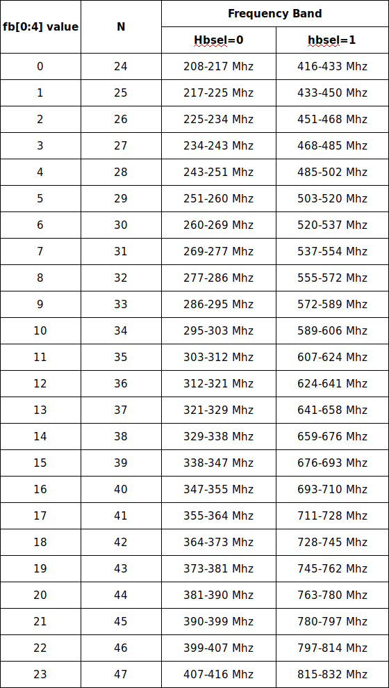
If, for example, we want to select the frequency 433.500Mhz, inside the 70cm radio amateur band, we have to select:


- hbsel=1 to select the higher band in the “re-scaled” table
- fb=1 to select the band between 433 and 450 Mhz
Next, according to the datasheet, we have to calculate the value of fc (Nominal Carrier Frequency) using the formula on the datasheet on page 22:
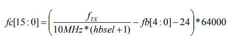
but again, this formula assumes a 30 Mhz crystal, instead we have a 26 Mhz crystal, this means that the value “10 Mhz” must be re-scaled multiplying it by 26/30 that gives 26/3, so the formula can be rewritten as:

Continuing with the example to set 433.500 Mhz this formula gives fc=615, rounded to the nearest integer, converting this value to hexadecimal gives 0x0267. This gives:


- register 0x76=0x02
- register 0x77=0x67
The register 0x75, according to the datasheet on page 22:
- bit 7 unused at value zero
- bit 6 is “sbsel” (Side Band Select) that, on the RS41 is at value 0. It is used only for RX configuration, but the RS41 transmits only, so this value doesn’t matter. The datasheet recommends to put this value to 1, but because the RS41 firmware put this value to 0, we can keep it at zero
- bit 5 is “hbsel” that is one in our case
- bit 4 to bit 0 are the “fb” (Frequency Band Select) that is 1 in our case
This gives:
- register 0x75=0x21
Putting all together in a simple Arduino subroutine we could write (please note that “reg75”, “reg76”, and “reg77” are global variables, array of char):
void calculateRegisters(float f) {
  float          fref=26.0 / 3.0;
  unsigned int   hbsel;
  unsigned int   fb;
  unsigned int   fc;

  Serial.println("-----> calculateRegisters");

  if (f >= 416.0) {
    hbsel = 1;
  } else {
    hbsel = 0;
  }

  fb = floor(f/(hbsel+1)*30.0/260-24);
  fc = round(64000.0*f/(fref*(hbsel+1)) - 64000.0*fb - 64000.0*24);
  Serial.print("frequency: ");Serial.println(f);
  Serial.print("hbsel:     ");Serial.println(hbsel);
  Serial.print("fb:        ");Serial.println(fb);
  Serial.print("fc:        ");Serial.println(fc);

  sprintf(reg75,"%02X",fb + hbsel * 32);
  sprintf(reg76,"%02X",fc/256);
  sprintf(reg77,"%02X",fc % 256);

  Serial.print("reg75      ");Serial.println(reg75);
  Serial.print("reg76      ");Serial.println(reg76);
  Serial.print("reg77      ");Serial.println(reg77);
}
Could someone share the UART commands to access the configuration menu??
Thanks!
Connect to the UART, run a terminal emulator, power up the radiosonde, wait for the string “Enabled TX”, wait another 1 or two seconds, then enter the string “STwsv”, followed by “Enter”.
The procedure is explained in great detail in the github page https://github.com/digiampietro/esp8266-rs41 related to a project to setup the desired frequency on the RS41 at the startup, using an esp8266 based board.
One question, I do not know much about this topic, if I make this change Temperature, Humidity, Height and GPS will be transmitted via the probe in 70 cm and it will be correct and it will not change when the power source is put on or not?
Thank you
George Migliarini California, USA (AC6RB)
Temperature, Humidity, Height, and GPS will be transmitted via the probe in 70 cm and this information will be correct, but if you power down the radiosonde and then power up this setup will be lost. This is explained in more detail on the GitHub page https://github.com/digiampietro/esp8266-rs41 related to a project to have this setup to survive power-down/power-up cycles adding an ESP8266 based board.